THE WORLD'S FUTURE
Femtotechnologies and Revolutionary Projects
By Alexander Bolonkin
2011
THE WORLD'S FUTURE
Femtotechnologies and Revolutionary Projects
By Alexander Bolonkin
2011
Contents
Preface
6. AB-Blanket for Cities
8. Magnetic Space Launchers
11. Magnetic Suspended AB-Structures and Motionless Satellites and Space Stations
and Flight (Part 1).
and Flight (Part 2).
and Flight (Part 3).
9. Robot as Person. Personhood. Three Prerequisites or Laws of Robots.
2. Data useful for estimation and calculation of new technologies and projects.
3. References
About the Author
Bolonkin, Alexander Alexandrovich (1933-)
Preface
The book gives the main physical data and technical equations in attachments which will help researchers, engineers, dedicated students and enthusiastic readers make estimations for their own macro-projects. Also, inventors will find an extensive field of inventions and innovations revealed in our book.
Every chapter is independent. Than why some figures are repited.
Part A. New Technology
Chapter 1
Converting of Matter to Nuclear Energy by
AB-Generator* and Photon Rocket
Abstract
The AB-Generator can produce gigantic energy outputs and should be cheaper than a conventional electric station by a factor of hundreds of times. One also may be used in aerospace as a photon rocket or as a power source for many vehicles.
Many scientists expect the Large Hadron Collider at CERN will produce one MBH every second.
A technology to capture them may follow; than they may be used for the AB-Generator.
* Presented as Paper AIAA-2009-5342 in 45 Joint Propulsion Conferences, 2-5 August, 2009, Denver, CO, USA.
Despite its invisible interior, a black hole can reveal its presence through interaction with other matter. A black hole can be inferred by tracking the movement of a group of stars that orbit a region in space which looks empty. Alternatively, one can see gas falling into a relatively small black hole, from a companion star. This gas spirals inward, heating up to very high temperature and emitting large amounts of radiation that can be detected from earthbound and earth-orbiting telescopes. Such observations have resulted in the general scientific consensus that, barring a breakdown in our understanding of nature, black holes do exist in our universe.
It is impossible to directly observe a black hole. However, it is possible to infer its presence by its gravitational action on the surrounding environment, particularly with microquasars and active galactic nuclei, where material falling into a nearby black hole is significantly heated and emits a large amount of X-ray radiation. This observation method allows astronomers to detect their existence. The only objects that agree with these observations and are consistent within the framework of general relativity are black holes.
A black hole has only three independent physical properties: mass, charge and angular momentum.
In astronomy black holes are classed as:
According to some theories of quantum gravity they may also be produced in the highly energetic reaction produced by cosmic rays hitting the atmosphere or even in particle accelerators such as the Large Hadron Collider. The theory of Hawking radiation predicts that such black holes will evaporate in bright flashes of gamma radiation. NASA's Fermi Gamma-ray Space Telescope satellite (formerly GLAST) launched in 2008 is searching for such flashes.
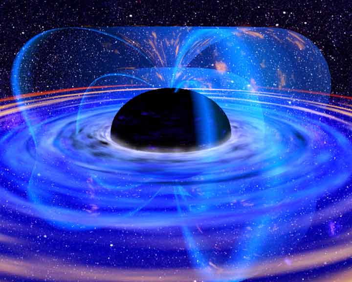
Fig 1. Artist's conception of a stellar mass black hole. Credit NASA.
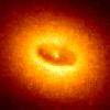
Fig.2 (left). Artist's impression of a binary system consisting of a black hole and a main sequence star. The black hole is drawing matter from the main sequence star via an accretion disk around it, and some of this matter forms a gas jet.
Fig.3 (right). Ring around a suspected black hole in galaxy NGC 4261. Date: Nov.1992. Courtesy of Space Telescope Science
For a non rotating (static) black hole, the Schwarzschild radius delimits a spherical event horizon. The Schwarzschild radius of an object is proportional to the mass. Rotating black holes have distorted, nonspherical event horizons. The description of black holes given by general relativity is known to be an approximation, and it is expected that quantum gravity effects become significant near the vicinity of the event horizon. This allows observations of matter in the vicinity of a black hole's event horizon to be used to indirectly study general relativity and proposed extensions to it.
Fig.4. Artist's rendering showing the space-time contours around a black hole. Credit NASA.
At the center of a black hole lies the singularity, where matter is crushed to infinite density, the pull of gravity is infinitely strong, and spacetime has infinite curvature. This means that a black hole's mass becomes entirely compressed into a region with zero volume. This zero-volume, infinitely dense region at the center of a black hole is called a gravitational singularity.
The singularity of a non-rotating black hole has zero length, width, and height; a rotating black hole's is smeared out to form a ring shape lying in the plane of rotation. The ring still has no thickness and hence no volume.
The photon sphere is a spherical boundary of zero thickness such that photons moving along tangents to the sphere will be trapped in a circular orbit. For non-rotating black holes, the photon sphere has a radius 1.5 times the Schwarzschild radius. The orbits are dynamically unstable, hence any small perturbation (such as a particle of infalling matter) will grow over time, either setting it on an outward trajectory escaping the black hole or on an inward spiral eventually crossing the event horizon.
Rotating black holes are surrounded by a region of spacetime in which it is impossible to stand still, called the ergosphere. Objects and radiation (including light) can stay in orbit within the ergosphere without falling to the center.
Once a black hole has formed, it can continue to grow by absorbing additional matter. Any black hole will continually absorb interstellar dust from its direct surroundings and omnipresent cosmic background radiation.
Much larger contributions can be obtained when a black hole merges with other stars or compact objects.
On the other hand if a black hole is very small, the radiation effects are expected to become very strong. Even a black hole that is heavy compared to a human would evaporate in an instant. A black hole the weight of a car (~10-24 m) would only take a nanosecond to evaporate, during which time it would briefly have a luminosity more than 200 times that of the sun. Lighter black holes are expected to evaporate even faster, for example a black hole of mass 1 TeV/c2 would take less than 10-88 seconds to evaporate completely. Of course, for such a small black hole quantum gravitation effects are expected to play an important role and could even - although current developments in quantum gravity do not indicate so - hypothetically make such a small black hole stable.
Theoretically this boundary is expected to lie around the Planck mass (~1019 GeV/c2, mp = 2.1764.10-8 kg), where quantum effects are expected to make the theory of general relativity break down completely. This would put the creation of black holes firmly out of reach of any high energy process occurring on or near the Earth. Certain developments in quantum gravity however suggest that this bound could be much lower. Some braneworld scenarios for example put the Planck mass much lower, maybe even as low as 1 TeV. This would make it possible for micro black holes to be created in the high energy collisions occurring when cosmic rays hit the Earth's atmosphere, or possibly in the new Large Hadron Collider at CERN. These theories are however very speculative, and the creation of black holes in these processes is deemed unlikely by many specialists.
Any primordial black holes of sufficiently low mass will Hawking evaporate to near the Planck mass within the lifetime of the universe. In this process, these small black holes radiate away matter. A rough picture of this is that pairs of virtual particles emerge from the vacuum near the event horizon, with one member of a pair being captured, and the other escaping the vicinity of the black hole. The net result is the black hole loses mass (due to conservation of energy). According to the formulae of black hole thermodynamics, the more the black hole loses mass the hotter it becomes, and the faster it evaporates, until it approaches the Planck mass. At this stage a black hole would have a Hawking temperature of TP / 8? (5.6в1032 K), which means an emitted Hawking particle would have an energy comparable to the mass of the black hole. Thus a thermodynamic description breaks down. Such a mini-black hole would also have an entropy of only 4? nats, approximately the minimum possible value.
At this point then, the object can no longer be described as a classical black hole, and Hawking's calculations also break down. Conjectures for the final fate of the black hole include total evaporation and production of a Planck mass-sized black hole remnant. If intuitions about quantum black holes are correct, then close to the Planck mass the number of possible quantum states of the black hole is expected to become so few and so quantised that its interactions are likely to be quenched out. It is possible that such Planck-mass black holes, no longer able either to absorb energy gravitationally like a classical black hole because of the quantised gaps between their allowed energy levels, nor to emit Hawking particles for the same reason, may in effect be stable objects. They would in effect be WIMPs, weakly interacting massive particles; this could explain dark matter.
Some extensions of present physics posit the existence of extra dimensions of space. In higher-dimensional spacetime, the strength of gravity increases more rapidly with decreasing distance than in three dimensions. With certain special configurations of the extra dimensions, this effect can lower the Planck scale to the TeV range. Examples of such extensions include large extra dimensions, special cases of the Randall-Sundrum model, and String theory configurations. In such scenarios, black hole production could possibly be an important and observable effect at the LHC.
Vacuum energy can also be thought of in terms of virtual particles (also known as vacuum fluctuations) which are created and destroyed out of the vacuum. These particles are always created out of the vacuum in particle-antiparticle pairs, which shortly annihilate each other and disappear. However, these particles and antiparticles may interact with others before disappearing.
The net energy of the Universe remains zero so long as the particle pairs annihilate each other within Planck time.
Virtual particles are also excitations of the underlying fields, but are detectable only as forces.
The creation of these virtual particles near the event horizon of a black hole has been hypothesized by physicist Stephen Hawking to be a mechanism for the eventual "evaporation" of black holes.
Since these particles do not have a permanent existence, they are called virtual particles or vacuum fluctuations of vacuum energy.
An important example of the "presence" of virtual particles in a vacuum is the Casimir effect. Here, the explanation of the effect requires that the total energy of all of the virtual particles in a vacuum can be added together. Thus, although the virtual particles themselves are not directly observable in the laboratory, they do leave an observable effect: their zero-point energy results in forces acting on suitably arranged metal plates or dielectrics.
Thus, virtual particles are often popularly described as coming in pairs, a particle and antiparticle, which can be of any kind.
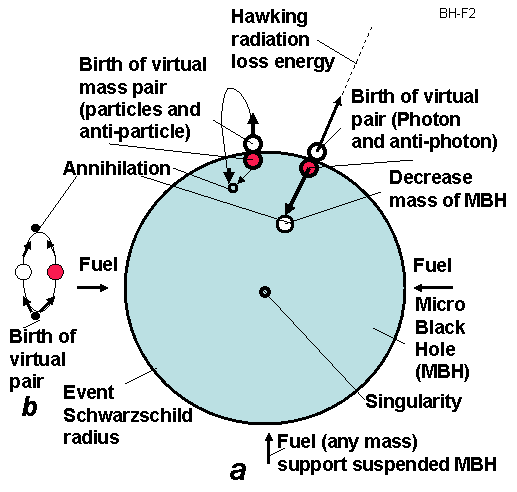
Fig.5. Hawking radiation. a. Virtual particles at even horizon.
b. Virtual particles out even horizon (in conventional space).
The uncertainty principle in the form
implies that in the vacuum one or more particles with energy ?E above the vacuum may be created for a short time ?t. These virtual particles are included in the definition of the vacuum.
AB-Generator of Nuclear Energy and some Innovations
Note: The photon does NOT have rest mass. Therefore a photon can leave the MBH's neighborhood (if it is located beyond the event horizon). All other particles having a rest mass and speed less than light speed cannot leave the Black Hole. They cannot achieve light speed because their mass at light speed equals infinity and requests infinite energy for its' escape--an impossibility.
Description of AB- Generator. The offered nuclear energy AB- Generator is shown in fig. 6. That includes the Micro Black Hole (MBH) 1 suspended within a spherical radiation reflector and heater 5. The MBH is supported (and controlled) at the center of sphere by a fuel (plasma, proton, electron, matter) gun 7. This AB- Generator also contains the 9 - heat engine (for example, gas, vapor turbine), 10 - electric generator, 11 - coolant (heat transfer agent), an outer electric line 12, internal electric generator (5 as antenna) with customer 14.
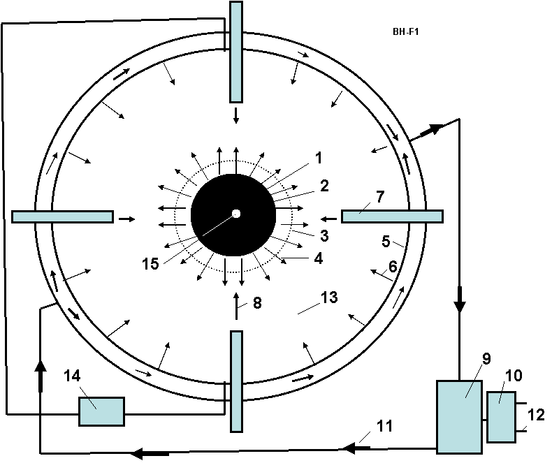
The control fuel guns inject the matter into MBH and do not allow bursting of the MBH. This action also supports the MBH in isolation, suspended from dangerous contact with conventional matter. They also control the MBH size and the energy output.
Any matter may be used as the fuel, for example, accelerated plasma, ions, protons, electrons, micro particles, etc. The MBH may be charged and rotated. In this case the MBH may has an additional suspension by control charges located at the ends of fuel guns or (in case of the rotating charged MBH) may have an additional suspension by the control electric magnets located on the ends of fuel guns or at points along the reflector-heater sphere.
Some problems and solutions offered by the author include the following:
2) MBHs may produce gigantic energy and this energy is in the form of dangerous gamma radiation. The author shows how this dangerous gamma radiation Doppler shifts when it moves
against the MBH gravity and converts to safely tapped short radio waves.
3) The MBH of marginal mass has a tendency to explode (through quantum evaporation, very quickly radiating its mass in energy). The AB- Generator automatically injects metered amounts of matter into the MBH and keeps the MGH in a stable state or grows the MBH to a needed size, or decreases that size, or temporarily turns off the AB- Generator (decreases the MBH to a Planck Black Hole).
4) Author shows the radiation flux exposure of AB- Generator (as result of MBH exposure) is not dangerous because the generator cover sphere has a vacuum, and the MBH gravity gradient decreases the radiation energy.
5) The MBH may be supported in a levitated (non-contact) state by generator fuel injectors.
Theory of AB- Generator
General theory of Black Hole.
1. Power produced by BH is
, W, (1)
is reduced Planck constant,
- light speed, G =
6.6743.10-11 m3/kg.s2 is gravitation constant, M - mass of BH, kg.
, K , (2)
where kb = 1.38.10-23 J/k is Boltzmann constant.
. (3)
where c = 3.108 m/s is light speed, ?o is wavelength of photon at even radius, m. h is Planck constant.
, m, (4)
, kg/m3. (5)
6. Maximal charge of BH is
, C, (6)
where e = -1.6.10-19 is charge of electron, C.
- -- Life time of BH is
2.527.10-8 M 3 , s . (7)
, m s-2 . (8)
Developed Theory of AB-Generator
Below are research and the theory developed by author for estimation and computation of facets of the AB- Generator.
9. Loss of energy of Hawking photon in BH gravitational field. It is known the theory of a redshift allows estimating the frequency of photon in central gravitational field when it moves TO the gravity center. In this case the photon increases its frequency because photon is accelerated the gravitational field (wavelength decreases). But in our case the photon moves FROM the gravitational center, the gravitational field brakes it and the photon loses its energy. That means its frequency decreases and the wavelength increases. Our photon gets double energy because the black hole annihilates two photons (photon and anti-photon). That way the equation for photon frequency at distance r > ro from center we can write in form
, (9)
. (10)
. (11)
It is known, the energy and mass of photon is
, (12)
The energy of photon linear depends from its frequency. Reminder: The photon does not have a rest mass.
. (13)
The ro is very small and ? is also very small and ? << ?o.
10. Reflection Hawking radiation back to MBH. For further decreasing the MBH produced energy the part of this energy may be reflected to back in MBH. A conventional mirror may reflect up 0.9 ¤0.99 of radiation (?r = 0.01 ¤ 0.1, ?r is a loss of energy in reflecting), the multi layers mirror can reflect up 0.9999 of the monochromatic light radiation (?r = 10-3¤ 10-5), and AB-mirror from cubic corner cells offered by author in [2], p. 226, fig.12.1g , p. 376 allows to reflect non-monochromatic light radiation with efficiency up ?r = 10-13 strong back to source. In the last case, the loss of reflected energy is ([2] p.377)
(14)
where l is size of cube corner cell, m; m is number of radiation waves in one sell; ? is wavelength, m; a is characteristic of sell material (see [2], fig.A3.3). Minimal value a = 10-2 for glass and a = 10-4 for KCl crystal.
The reflection of radiation to back in MBH is may be important for MBH stabilization, MBH storage and MBH `switch off'.
11. Useful energy of AB- Generator. The useful energy Pu [J] is taken from AB- Generator is
. (15)
, kg. (16)
The fuel consumption is very small. AB-Generator is the single known method in the World now which allows full converting reasonably practical conversion of (any!) matter into energy according the Einsteinian equation E = mc2.
13. Specific pressure on AB-Generator cover sphere p [N/m2] and on the surface of MBH po is
, (17)
the radiation, S is the internal area of cover sphere, m2; S0 is surface of event horizon sphere, m2; po is
specific pressure of Hawking radiation on the event horizon surface. Note, the pressure p on cover
sphere is small (see Project), but pressure po on event horizon surface is very high.
14. Mass particles produced on event surface. On event horizon surface may be also produced the mass particles with speed V < c. Let us take the best case (for leaving the BH) when their speed is radially vertical. They cannot leave the BH because their speed V is less than light speed c. The maximal radius of lifting rm [m] is
, (18)
where g is gravitational acceleration of BH, m/s2; t is time, sec.; ro is BH radius, m; V0 is particle
. (19)
. (20)
, (21)
where V=3/4 ?r3 is volume of the cover sphere.
Your attention is requested toward the next important result following from equations (20)-(21). Many astronomers try to find (detect) the MBH by a MBH exposure radiation. But this radiation is small, may be detected but for a short distance, does not have a specific frequency and has a variably long wavelength. This may be why during more than 30 years nobody has successfully observed MBH events in Earth environment though the theoretical estimation predicts about 100 of MBH events annually. Observers take note!
The maximal suspended force equals
, (22)
where q is fuel consumption, kg; Vf is a fuel speed, m/s. The fuel (plasma) speed 0.01c is
(23)
where w is density of radiation energy, J/m3; E is electric intensity, V/m; H is magnetic intensity, T; ?o = 8.85в10-12 F/m is the coefficient of the electric permeability; ?o = 4?в10-7 N/A2 is the coefficient of the magnetic permeability; ? = ? =1 for vacuum.
Let us take moment when H = 0, then
(24)
where E is electric intensity, V/m; U is voltage of AB-generator, V; b is relative size of antenna, D is diameter of the cover sphere if the cover sphere is used as a full antenna, m; Pe is power of the electric station, W.
As you see about ?/4 of total energy produced by AB-Generator we can receive in the form of electricity and (1-?/4) reflects back to MBH; we may tap heat energy which convert to any form of energy by conventional (heat engine) methods. If we reflect the most part of the heat energy back into the MBH, we can have only electricity and do not have heat flux.
If we will use the super strong and super high temperature material AB-material offered in [3] the conversion coefficient of heat machine may be very high.
(25)
where V is speed of environment matter absorbed by MBH, m/s; g is gravity acceleration of MBH, m/s; r is distance environment matter to MBH center, m; t is time, sec;
is mass loss by MBH, kg;
is mass taken from Earth environment by MBH, kg; ? is density of Earth environment, kg/m3; Mc is critical mass of MBH when one begin uncontrollable grows, kg; t is time, sec.
radiated by MBH to mass
absorbed by MBH from Earth environment, we obtain the critical mass Mc of MBH for any environment:
, (26)
19. General note. We got our equations in assumption ?/?o = r/ro. If ?/?o = (r/ro )0.5 or other relation, the all above equations may be easy modified.
AB-Generator as Photon Rocket
The some possible photon propulsion system used the AB -Generator is shown in Fig.7. In simplest version (a) the cover of AB generator has window 3, the radiation goes out through window and produces the thrust. More complex version (c) has the parabolic reflector, which sends all radiation in one direction and increases the efficiency. If an insert in the AB- Generator covers the lens 6 which will focuses the radiation in a given direction, at the given point the temperature will be a billions degree (see Equation (2)) and AB- Generator may be used as a photon weapon.
The maximal thrust T of the photon engine having AB- Generator may be computed (estimated) by equation:
, N, (26)
For example, the AB-generator, which spends only 1 gram of matter per second, will produce a thrust 3в105 N or 30 tons.
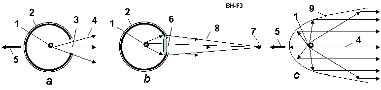
Fig.7. AB- Generator as Photon Rocket and Radiation (Photon) Weapon. (a) AB- Generator as a Simplest Photon Rocket; (b) AB- Generator as focused Radiation (photon, light or laser) weapon; (c) Photon Rocket with Micro-Black Hole of AB-Generator. Notations: 1 - control MBH; 2 - spherical cover of AB-Generator; 3 - window in spherical cover; 4 - radiation of BH; 5 - thrust; 6 - lens in window of cover; 7 - aim; 8 - focused radiation; 9 - parabolic reflector.
Project of AB-Generator
(27)
Remain the main notations in equations (27): Pr = Pu = 1.05в1010 W is the useful energy (?/4 of this energy may be taken as electric energy by cover antenna, the rest is taken as heat); ? = 80 m is wavelength of radiation at cover sphere (that is not dangerous for people);
= 1.17в10-7 kg/s is fuel consumption; ro = 1.48в10-32 m is radius of MBH; pe = 1.28в10-23 N/m2 is explosion pressure of MBH.
Look your attention - the explode pressure is very small. That is less in billions of time then radiation pressure on the cover surface p = 0.111 N/m2. That is no wonder because BH takes back the energy with that spent for acceleration the matter in eating the matter. No dangerous from explosion of MBH.
(28)
where q is specific heat transfer through the cover sphere, S is internal surface of the cover sphere, m2; ? is thickness of the cover sphere wall, m; ?h is heat transfer coefficient for steel; ?T is difference temperature between internal and external walls of the cover sphere; E is electric intensity from radiation on cover sphere surface, V/m; U is maximal electric voltage, V; Pe is electric power, W.
We get the power heat and electric output of a AB-Generator as similar to a very large complex of present day Earth's electric power stations (Pr = 1010 W, ten billion of watts). The AB-Generator is cheaper by a hundred times than a conventional electric station, especially since, we may reflect a heat energy back to the MBH and not built a heat engine with all the problems of conventional power conversion equipment (using only electricity from spherical cover as antenna).
We hope the Large Hadron Collider at CERN can get the initial MBH needed for AB-Generator. The other way to obtain one is to find the Planck MBH (remaining from the time of the Big Bang and former MBH) and grow them to target MBH size.
2. The Micro Black Hole (MBH) is offered for this conversion.
5. Also is offered the control fuel guns and radiation reflector for non-contact suspension (levitation)
of the MBH.
6. For non contact levitation of MBH the author also offers:
a) Controlled charging of MBH and of ends of the fuel guns.
b) Control charging of rotating MBH and control of electric magnets located on the ends of the fuel
guns or out of the reflector-heater sphere.
7. The author researches show the very important fact: A strong gamma radiation produced
by Hawking radiation loses energy after passing through the very strong gravitational MBH
field. The MBH radiation can reach the reflector-heater as the light or short-wave radio radiation.
That is very important for safety of the operating crew of the AB- Generator.
8. The author researches show: The matter particles produced by the MBH cannot escape from MBH
and can not influence the Hawking radiation.
9. The author researches show another very important fact: The MBH explosion (hundreds and
very important for safety of the operating crew of the AB-generator.
10. The author researches show another very important fact: the MBH cannot capture by oneself
the surrounding matter and cannot automatically grow to consume the planet.
11. As the initial MBH can be used the Planck's (quantum) MBH which may be everywhere.
The offered fuel gun may to grow them (or decrease them) to needed size or the initial MBH may
be used the MBH produce Large Hadron Collider (LHC) at CERN. Some scientists assume LHC
will produce one MBH every second (86,400 MBH in day). The cosmic radiation also produces
about 100 MBH every year.
12. The spherical dome of MBH may convert part of the radiation energy to electricity.
We got our equations in assumption ?/?o = r/ro. If ?/?o = (r/ro )0.5 or other relation, the all above equations may be easy modified.
The Hawking article was published 34 years ago (1974)[1]. After this time the hundreds of scientific works based in Hawking work appears. No facts are known which creates doubts in the possibility of Hawking radiation but it is not proven either. The Hawking radiation may not exist. The Large Hadron Collider has the main purpose to create the MBHs and detect the Hawking radiation.
(The reader may find some of related articles at the author's web page http://Bolonkin.narod.ru/p65.htm; http://arxiv.org , http://www.scribd.com search "Bolonkin"; http://aiaa.org search "Bolonkin"; and in the author's books: "Non-Rocket Space Launch and Flight", Elsevier, London, 2006, 488 pages; "New Concepts, Ideas, Innovations in Aerospace, Technology and Human Science", NOVA, 2008, 502 pages and "Macro-Projects: Environment and Technology", NOVA 2009, 536 pages).
2. Bolonkin A.A., Non-Rocket Space Launch and Flight, Elsevier, 2006, 488 pgs.
Commons license. http://wikipedia.org .
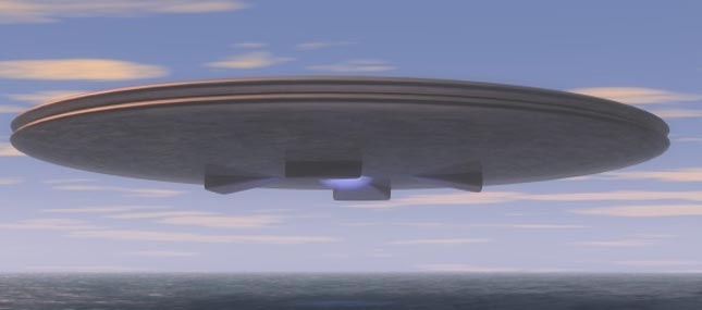
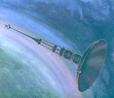
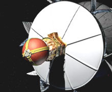
Possible form of photon rocket
Femtotechnology: the Strongest AB-Matter with Fantastic Properties
and their Applications in Aerospace
Abstract