I look for a sponsor, investor or partner to implement the Innovations claimed by me.
Koganitsky adiabatic engine
All drafts used in this description are simplified sketches without minor details.
To click will enlarge a picture.
Innovations claimed by the author as his intellectual property
- --
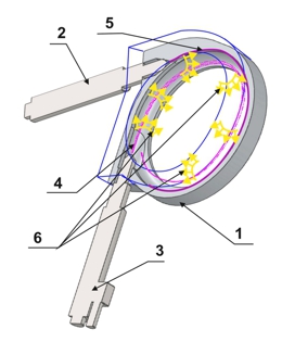
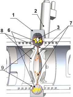
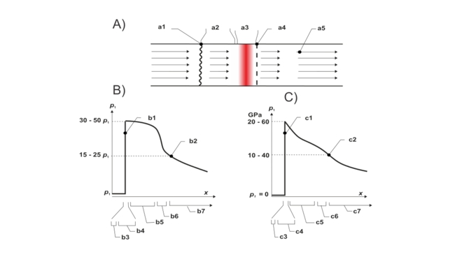
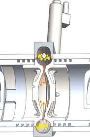
Initiation and realization of highly efficient combustion of fuel by a detonation front moving in the form of an annular vortex flow in a toroidal-slit structure of variable volume;
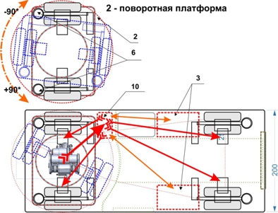
- -- Usage in the valveless two-cycle engine of a flue damper or a rotating valve, which briefly covers the exhaust path, from the moment before the end of the exhaust gas "release" phase, until the moment of complete overlap an exhaust piston edge for realization of a back kick of high pressure into the exhaust path of a cylinder;
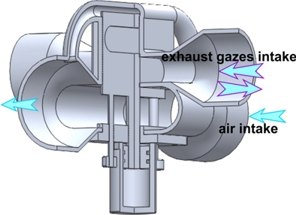
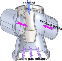
- -- Sucking liquid coolant from the cylinders in the injector pomp under the action of high-temperature exhaust gases of the engine and generation by them gas-vapor mixture;
- -- The energy utilization of exhaust gases and heat which produced by the engine through the gas-vapor mixture working in the differential turbine.
- -- Usage in the valveless two-cycle engine of a flue damper or a rotating valve, which briefly covers the exhaust path, from the moment before the end of the exhaust gas "release" phase, until the moment of complete overlap an exhaust piston edge for realization of a back kick of high pressure into the exhaust path of a cylinder;
|
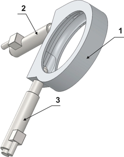
Toroidal combustion chamber in the cylinder head |
||
 |
 |
 |
|
|
||
|
|
|
|
|
 |
 |
 |
 |
|
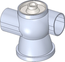
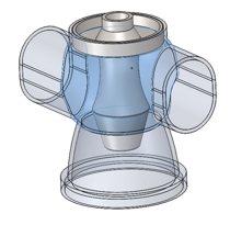
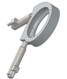
injection pump
|
|
|
|
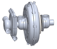
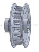
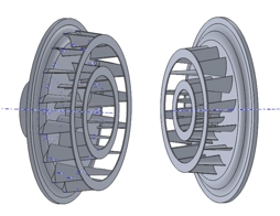
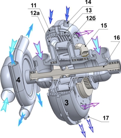
The condensation, differential turbine |
||
 |
 |
 |
|
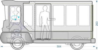
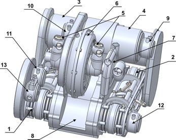
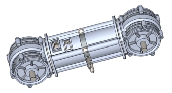
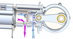
An example of a two-cycle, hybrid engine with a vortex detonation combustion chamber |
||
 |
 |
 |
|
|
|
|
|
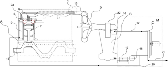
Example of a stationary diesel upgrade
|
|
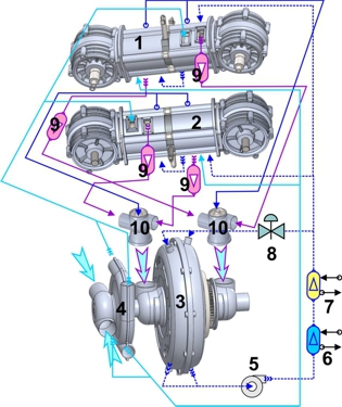 |
 exhaust gazes  coolant  compressed air  steam condensate gas-vapor mix air after heat exchanger |
|
|
|
|
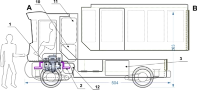
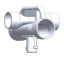
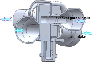
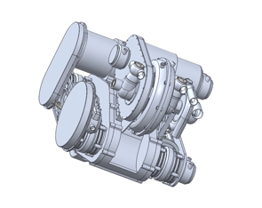
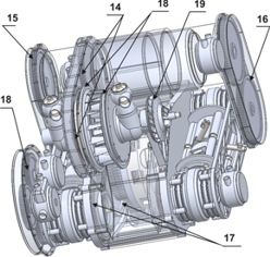
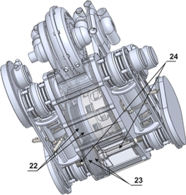
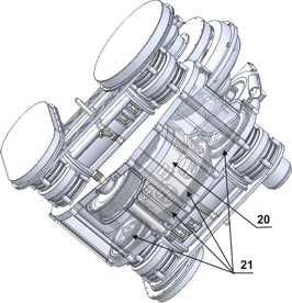
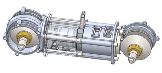
Engine design |
||
|
|
 |
 |
 |
|
 |
|
|
||
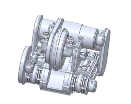
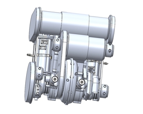
Unified Diesel Module
|
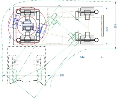
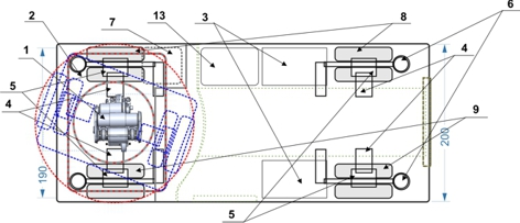
Design of a diesel module |
|
|
|
|
|
|
|
|
|
|
|
|
|
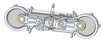
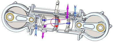
The diesel module works as follows
|
|
|
|
|
|
|
|
|
|
|
|