Method of forming in Space of the inflatable module with an inner protective layer of a composite material consisting of synthetic filaments and water-ice
"Method of forming in Space of the inflatable module with an inner protective layer of a composite material consisting of synthetic filaments and water-ice"
This method is based on physical principles:
1. Constancy of a partial vapor pressure at a predetermined temperature;
2. Sublimation of water vapor in a vacuum onto physical objects.
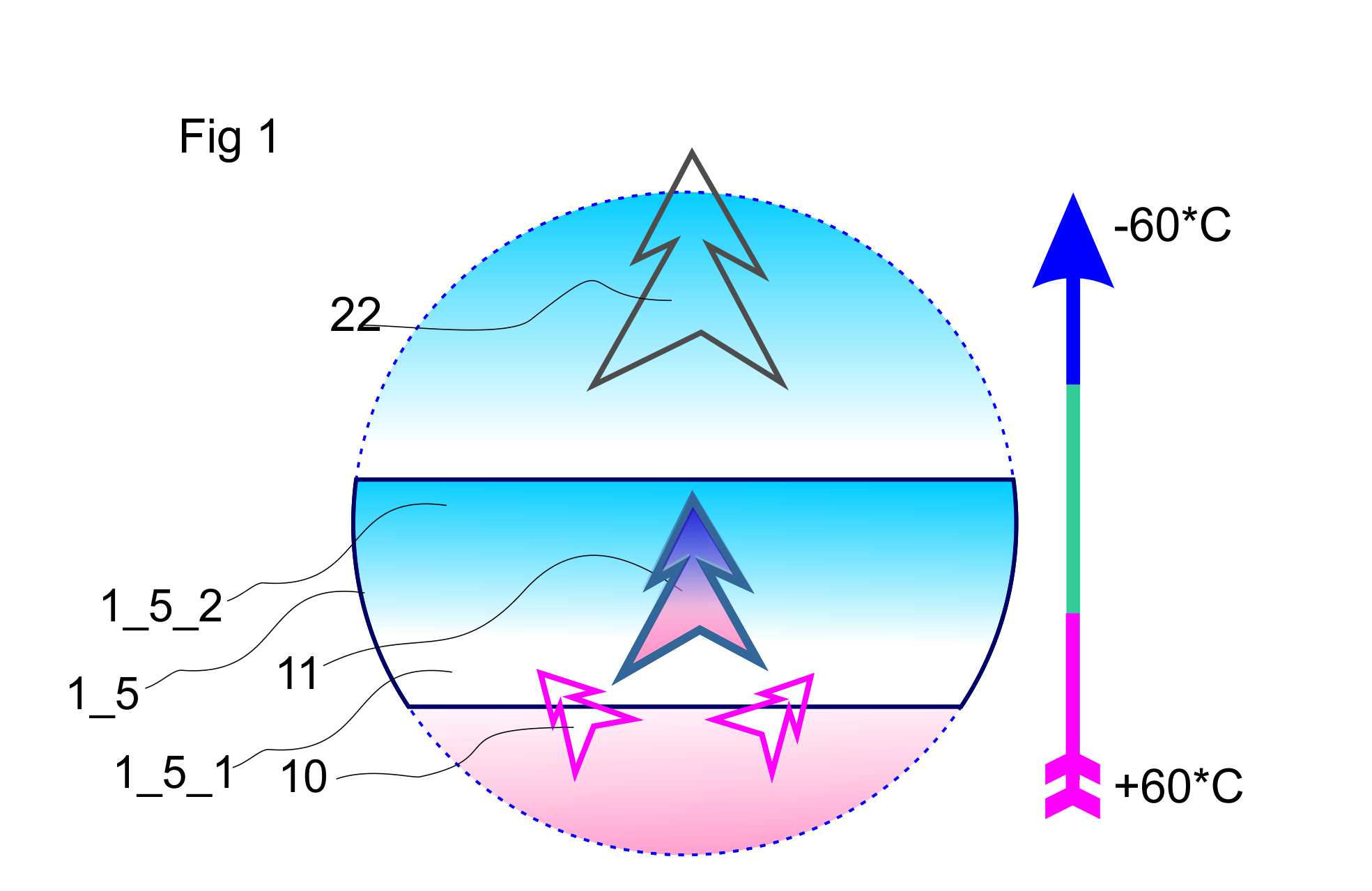
When a water vapor is feed into the sponge of fine-wool synthetic filaments (such as - high density polyethylene filaments), water vapor moved along the temperature gradient in the direction to more cooled area, regardless of the presence and direction of gravity.
At the beginning of the sublimation, Ice is sublimed on the filaments and forms an ice cover on each filament, with the spaces between the filaments which are filled by the supercooled water vapors.
1_5 ice composite, 1_5_1 water-steam phase; 1_5_2 crystals of ice; 10 boost of water vapor; 11 temperature gradient; 22 dropping of heat
After filaments of the composite sponge are coated with sufficient amount of ice, the composite sponge is compressed and further cooled.
As a result, it is transformed into homogenous composite material of high strength.
According to preliminary estimates, such the composite material having thickness of three centimeters (before compression - five centimeters) with a specific gravity of 1-1.1 has the strength and ability to absorb radiation of a medium-energy equal to a steel shell of 6-8mm thickness.
The capacity for radiation absorption can be increased by the insertion into the sponge (in dry state) of fine barium sulfate powder.
The important features of such a composite material - the ability of self-repairing of all types of chips and cracks which don't violate the hermeticity of the shell and the ability to form a temporary plug, without assistance, for repairing of a through breakdown of the shell of module that is located in a vacuum, if the diameter of the holes is less than 1/3 of the thickness of the composite material.
The module for the Space station, which is designed on basis of this technique, is transformable and having possibility changing of volume in preparation for the exploitation.
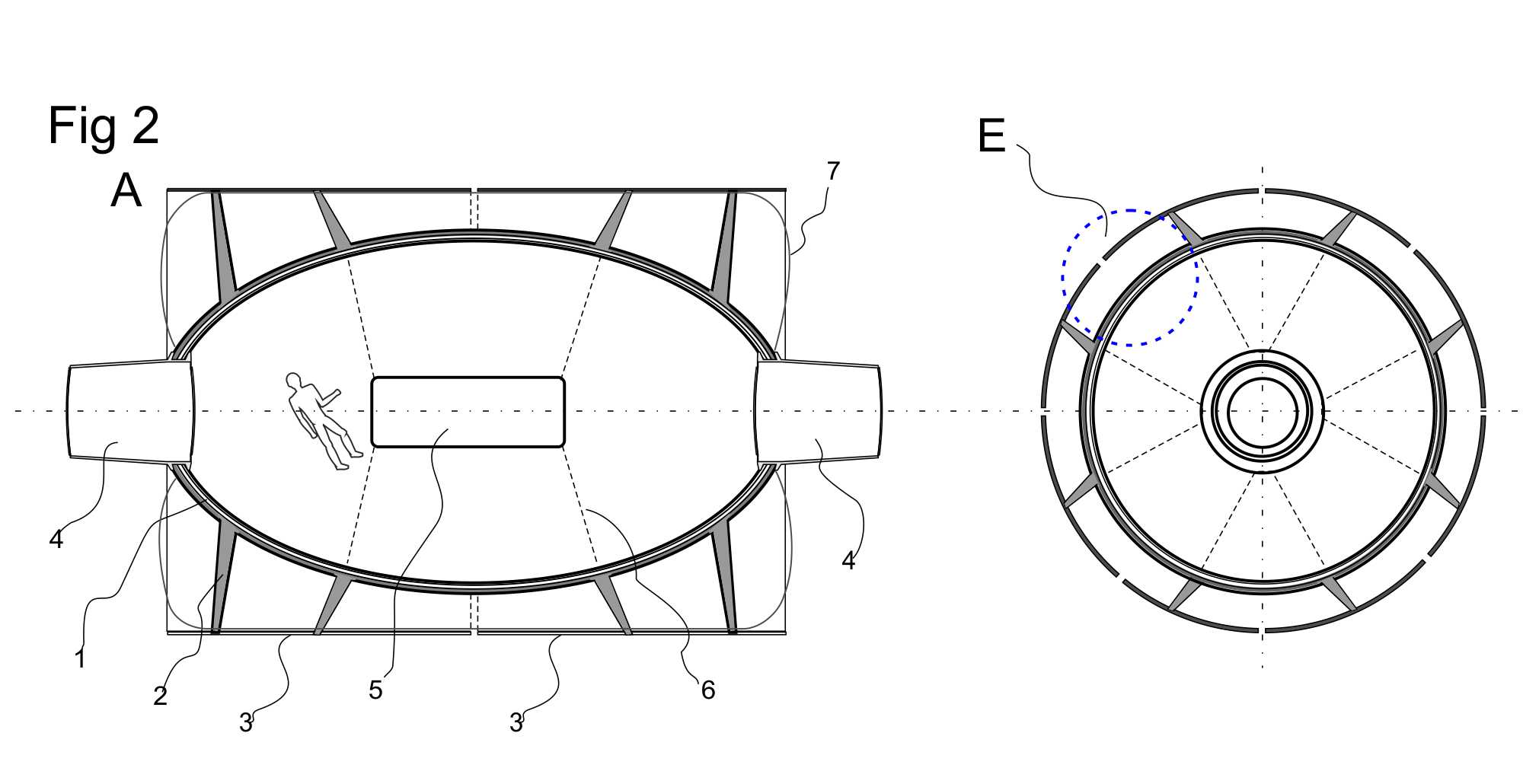
Fig 2 the module in working state
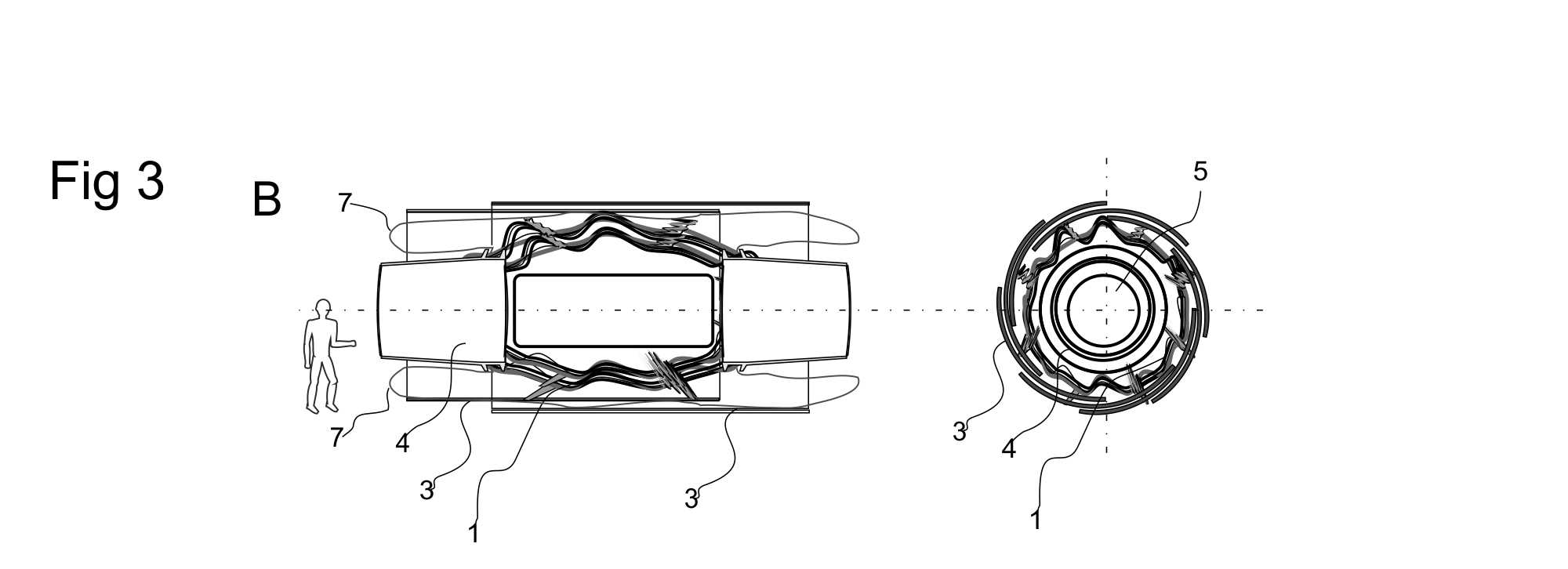
Fig 3 the module in the transport state
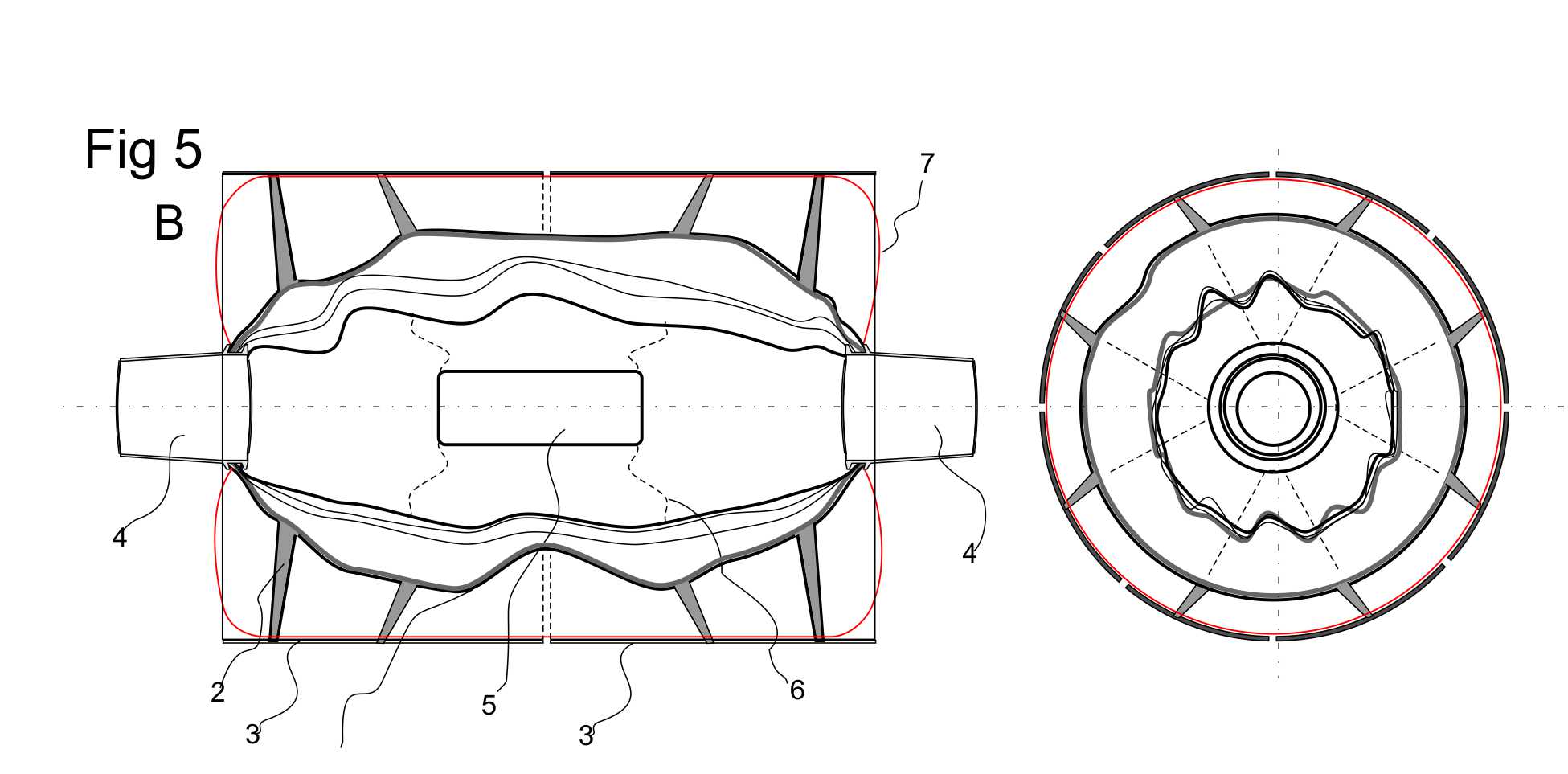
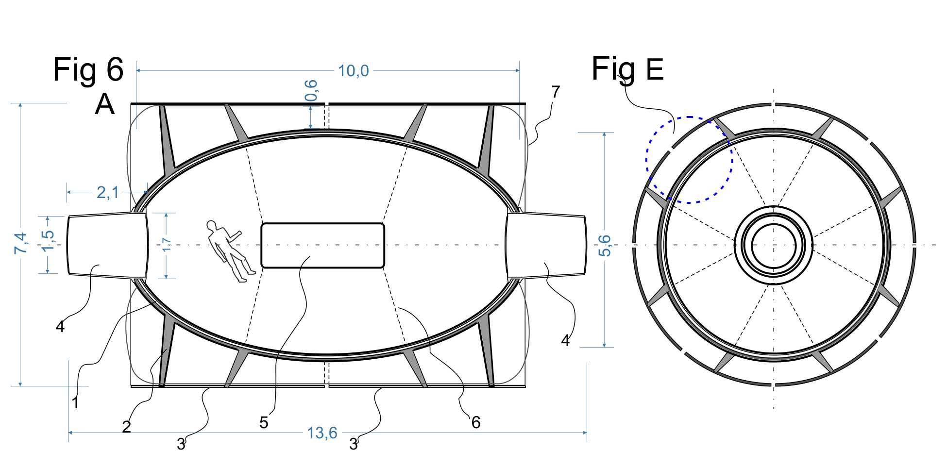
1 shell of the module ; 2 racks; 3 solar panel-heat exchanger; 4 gateways; 5 hardware module; 6 tension bracing; 7 a shell of low strength; E cross-section of module's shell
The module consists of the strong hull that is a flexible, in a transport state and rigid in a operation state and has the sluice chambers which are located in its ends.
The outer shell of the hull has magnetic properties and a mini self-propelled handling device can move on it by magnetic caterpillars.
In the transport state lock chambers work as thermoses of hot water and storages of working substances.
The strong shell is encased in a lightweight shell of low strength, which operates only during of the transformation of the module from the transport state to the operating state.
After performing the transformation, this shell can be disintegrated.
Both shells are covered by the composite cylinder consisting of the individual solar cells that serve also and as a heat removal for thermal tapes of cooling of the shell of the composite material.
The solar cylinder is attached to the strong shell by inflatable struts, made by the same technology as the shell.
In the transport state, the individual solar cells stacked on the principle of unblown flower head.
The transformation from the transport state into the working state takes place as follows (dimensions are given only for demonstration and comparison).
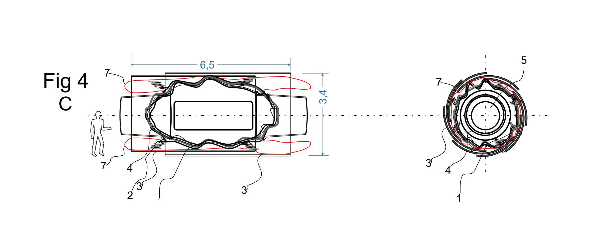
Fig 4.
The module 1, for preparing for launching, is packed into a compact packet and is vacuumized.
The lightweight shell 7, under the pressure of the atmosphere, takes the form of "minimum volume" that densely covers the strong shell.
Solar panels 3 assembled in two 'buds' and shifted into each other.
Gateways 4 that work as thermos for hot water and working substances is maximum retracted inside the package.
Fig 5.
After reaching its operational orbit, the module separates from the carrier, and performs supercharging of the shell 7 by low-pressure gas.
Presumably, the operating pressure in the shell 7, which is required for the first phase of the deployment of the module, will be in the range of 0.2-0.3 atm.
Under the influence of the overpressure in the shell 7, it is inflated and moves apart gateways 4 and solar panels 3 moving them into working position.
Fig 6
At the final stage of deployment, the module carries out filling of composite by ice taking the specified working form of and the necessary rigidity.
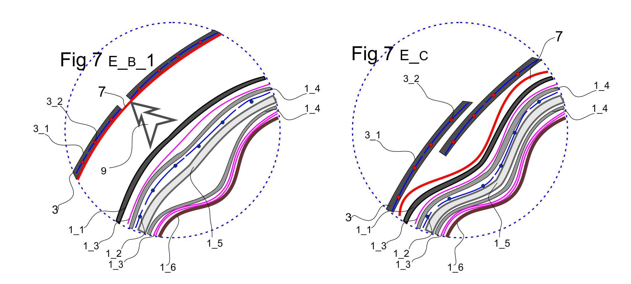
Fig 7
Deploying of the module is performed as follows
The module has several coaxial shells, which can be divided into two main groups: the cylinder of photo panels-heat exchangers 3, which provides the energy needs of the station and the necessary thermal conditions for its functioning; and the main shell 1.
Fig 7 E_B_C
The shell 7 is auxiliary and serves only for an initial deploy of stations and deploy of solar panels 3 by influence of pressurized gas 9.
Fig 7 E_B_1
When the shell 7 is inflated, solar panels take up working position and by action of racks 2 which are fixed as at robust housing 1 and, through the shell 7, at the solar panels, shell 1 partially takes form and smoothes.
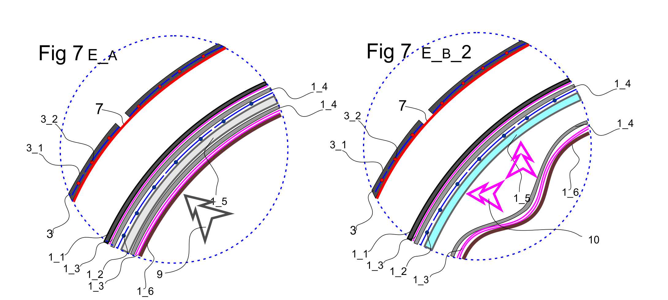
The cylinder of solar panels-heat exchanger consists of separate multilayer panels. Each panel has a layer of solar cell 3_1, a layer of semiconductor thermoband 3_2 and layer of heat reflecting matter 3_3.
Strong shell 1 is multi-layered and consists of: an outer hermetic shell 1_1; two heat-reflecting layers 1_3; two insulation layers 1_4; sponge of synthetic filaments, from which will be formed composite layer 1_5; inner shell 1_6
In the transport state, all layers of shell are situated in maximally dense packaging.
Solar panels are collected as "buds".
After pressurization of shell 7, solar panels take the working position.
After solar power panels began to generate energy and begin to carry out cooling of the fibrous substrate of the composite, system of module begin injection of hot water 10 into the inner layers of shell, which are under vacuum, and as a result of that, they will be pressurized by steam that is generated from hot water in vacuum.
Fig 7 E_A
After completion of the formation of the composite layer 1_5 of shell 1 and racks 2, the inner layer of the shell 1 is inflated by air to the operating pressure and as result, the composite layer will be compressed out to the working thickness and then this layer is cooled to the working temperature by thermal tapes 1_3.
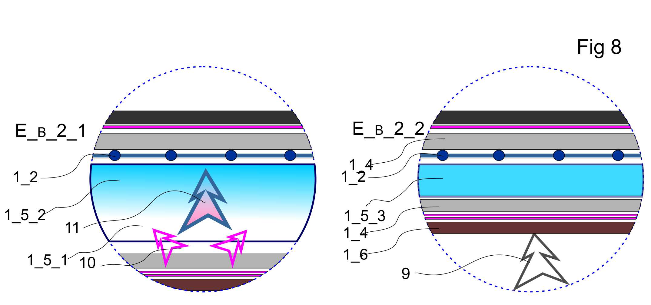
Formation of the composite layer carried out as follows
Fig 8 E_B_2_1
A hot water 10 is supplied into interlayer space of strong shell 1 of the module which has already been pre-deployed by supercharging of auxiliary shell 7.
When water is evaporated into vacuum it generates steam, partial pressure of which is dependent on temperature.
Simultaneously with generation of steam, thermal tapes 1_2 begin to cooling the outer side of the future composite, creating a temperature gradient 11 inside of it and, respectively, the gradient of partial pressure, along which the movement of water molecules occurs 1_5_1 -> 1_5_2.
At the initial stage, temperature of the composite is changed from 0 to -5 * C.
/ Here and below, all numerical values are for illustrative purposes only and were selected tentatively /
Composite filaments begin to be covered by ice covers, between which supercooled water condensate is located.
At this stage, the composite consists of a low density ice that is reinforced by filaments - its look like granular wet snow.
Fig 8 E_B_2_2
After filling of filaments of the composite by ice, thermal tapes begin to reduce temperature of the composite to -60 * C, simultaneously with increasing the pressure 8 at the inner shell 1_6.
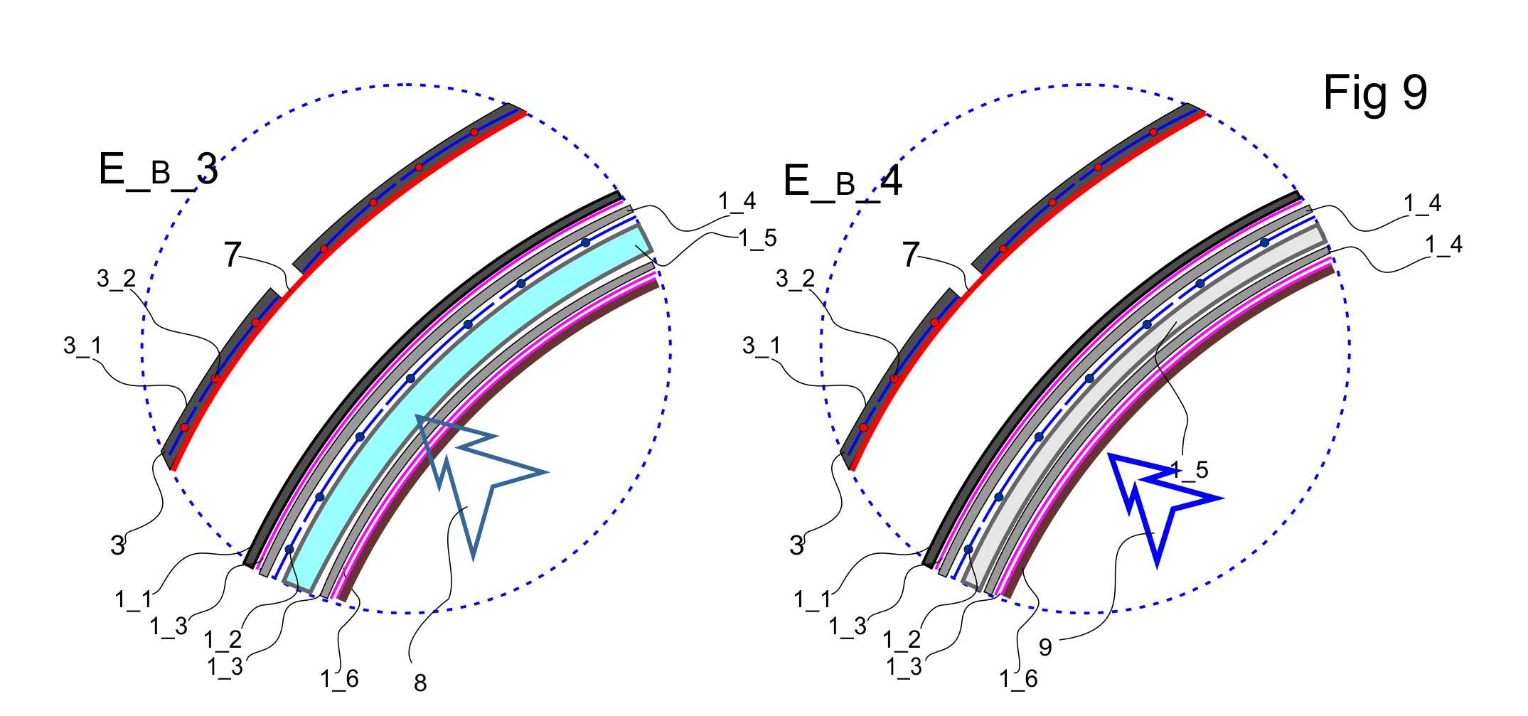
Fig 9 E_B_3
Under the influence of external pressure, the composite and its surrounding shells are compressed in the radial direction, and simultaneously with lowering of the temperature, granular ice is consolidated and transformed into ice high density.
Fig 9 E_B_3
After completion of high density ice formation and stabilization of temperature throughout volume of the composite, air pressure inside the module rises to operating level 9.
The module is in mode of "ready for operation"
The used methodology allows creating orbital structures which can be changed during exploitation (fulfilment of reforming) and be adapted to new requirements.
As mentioned above, this type of composite material has high maintainability, including the ability to self-repair.
Damage to the composite without breaking of the shell tightness, such as cleavages and cracks can self liquidated after of the disappearance of a source of stress by of mutual diffusion of its surfaces which are pressed against each other.
To eliminate large damage, thermal tapes placed near the damaged area can temporarily increase the temperature of the composite up to a plastic state.
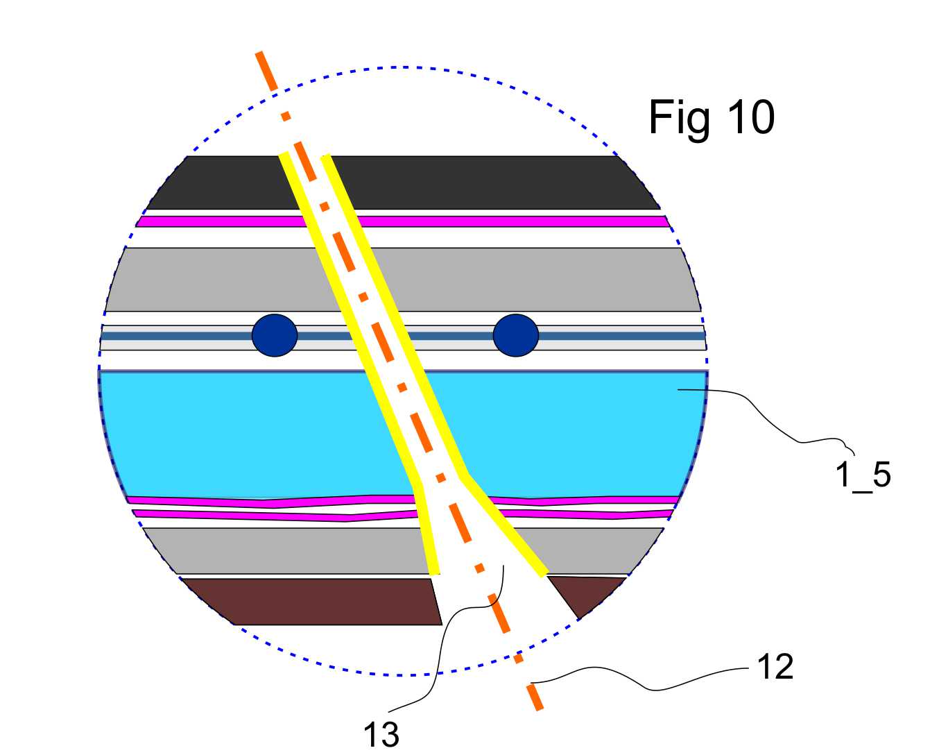
Elimination of a through hole in the leakproofness shell is carried out as follows.
Fig10
Consider a hypothetical case of a breakdown of micrometeorite through the shell in which formed sloping channel 12 with a diameter of 10mm.
The channel is covered by melted and destroyed material of shell and has an expanded outlet.
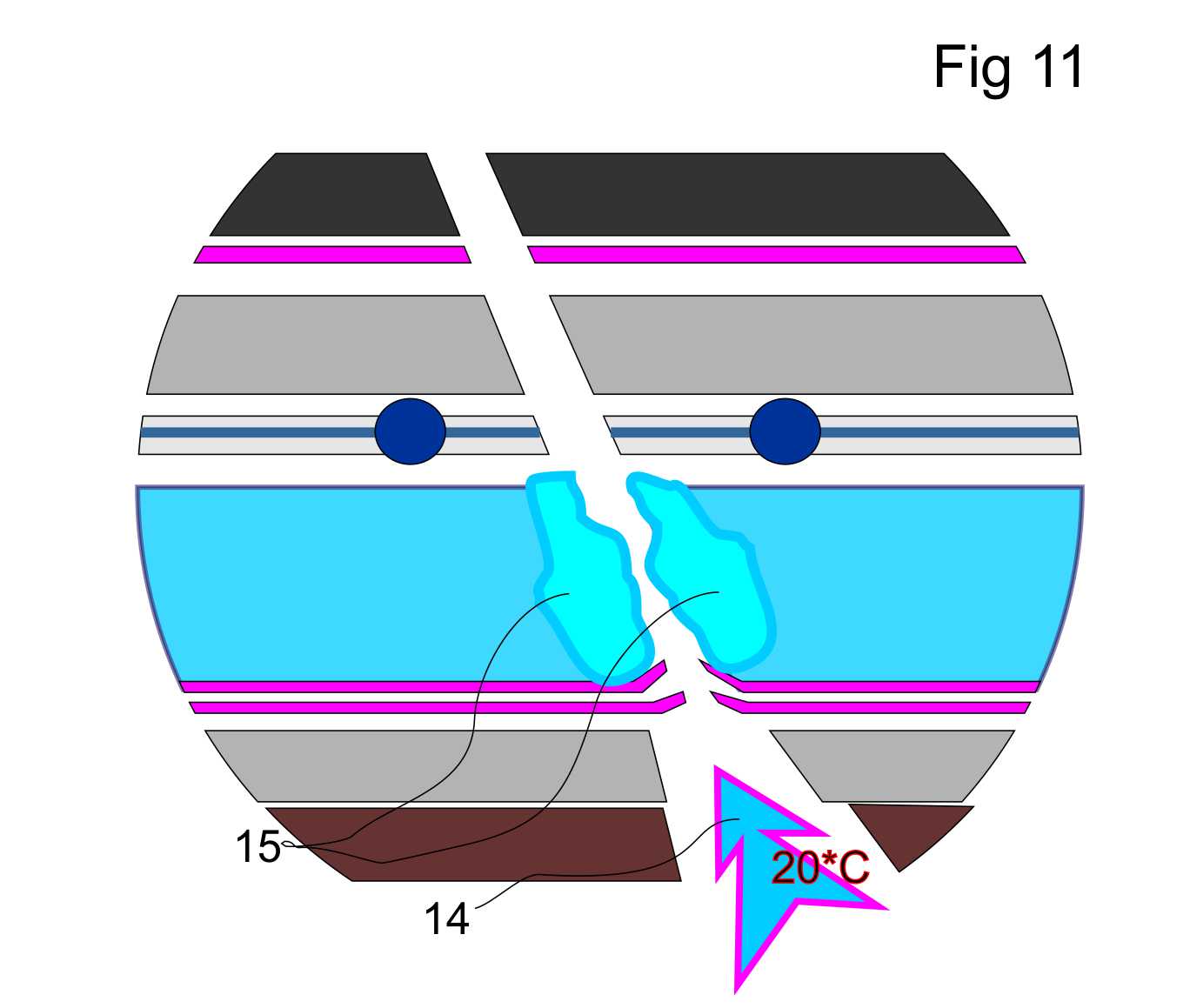
Fig11
As a result of the breakdown through the shell, the internal atmosphere 14 of the module, which have temperature of 20*C, begins outflow into Space through the composite material of the shell.
As a result of heating of the composite material in the breakdown zone by air flow, the composite transforms into a plastic state and its filaments begin to get smoothed out.
The smoothed out filaments 15 are drawn into the air flow of channel 14, partially blocking the flow and creating in the channel along its length of the pressure difference.
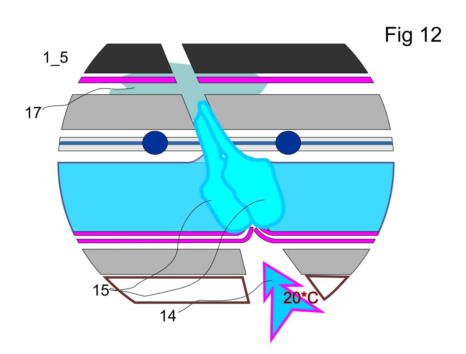
Fig12
Water and ice particles are filtered through filaments and, as result of increasing of dynamic resistance of flow, begin to evaporate in the vacuum zone, reducing the temperature of filaments of the composite drawn-in in channel 15.
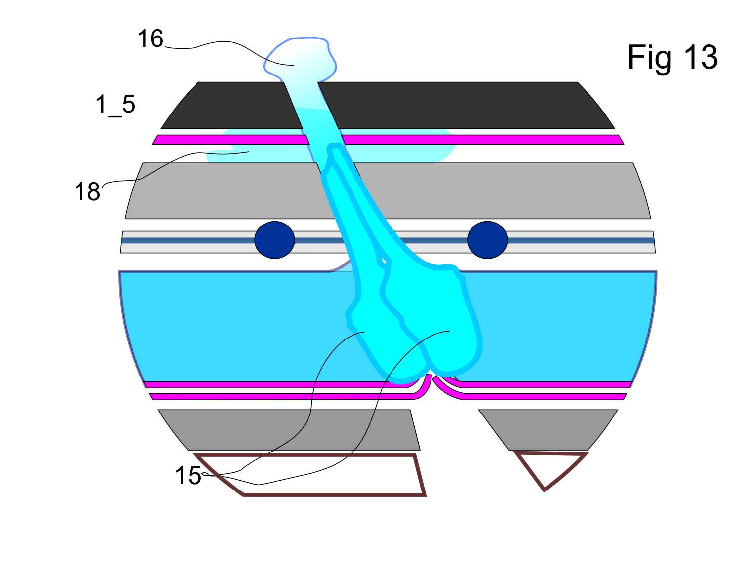
Fig13
As a result of this cooling, crystals of ice 17 begin to sublimate between filaments and between shell's layers.
Under the pressure of the air stream, from the sponge that was formed from ice and filaments and are pressed into the breakthrough zone, is formed partially hermetic cork 15.18 inside of channel 13.
Ice and water 16 infiltrating through the partially hermetic cork and are sublimated in the end of the breakdown carry out further lowering the temperature until moment when dynamic equilibrium will be established in the temperature range about minus 140-160 * C.
By this time, air leakage through the tightened cork is practically stopped without requiring the adoption of emergency measures and it gives to the crew sufficient time to eliminate the consequences of the accident.
The crew carries out the following action to completely stop the leak and to restore the shell.
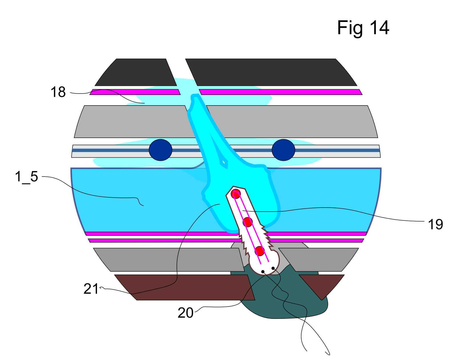
Fig14
The thermocouple probe 19 must be entered in the channel and the inner hole is sealed by a two-layer (a solid layer + an insulation layer) self-hardening stopper 20.
The thermocouple probe 19 begins to heat and to vibrate, as a result of this, it being displaced through ice to the outer shell.
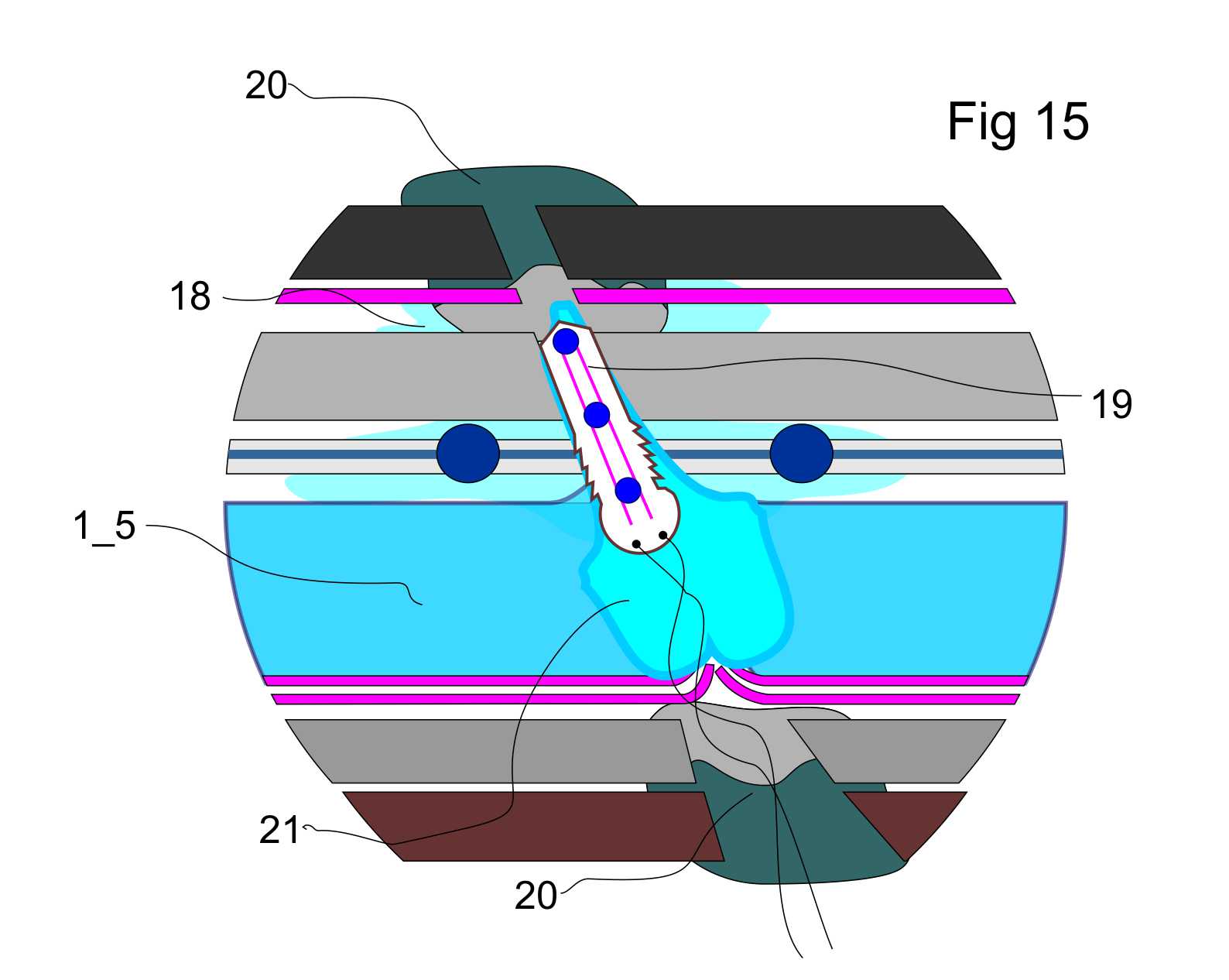
Fig15
Reaching of the outer insulating layer, the thermocouple probe 19 is switched to the cooling and it is ice-bound into the ice plug, compensating in this place a damaged thermal tape.
With the help of a self-propelled outdoor manipulator, crew carry out pasting of the outer opening by usage of self-hardening stopper 20, stopping the sublimation of ice from the holes.
The offered technology and the basic module based on it allow creating a mobile Space station with a resource of self-contained operation 8-10 years.
.
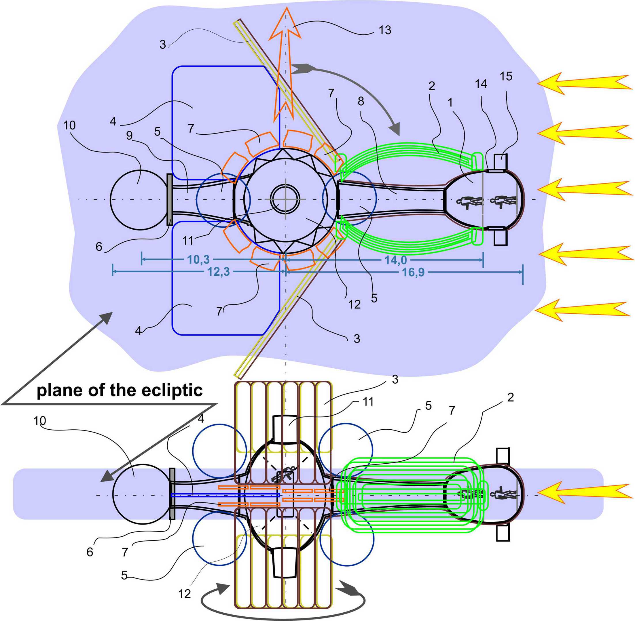
As an example, the mobile Space Station of the carousel's design which has the pulsed ion engines
1 habitable module; 2 a seawater biosystem; 3 solar panels-heat exchangers; 4 heat exchangers; 5, water and fuel tanks; 6 biological shield; 7 cassette of pulsed ion engines; 8 tunnel of greenhouses; 9 tunnel of dirty technologies; 10 isotope battery; 11 gateway; 12 main operating module; 13 impulse ion engines; 14 flexible gateway; 15 technological platform.
The station is powered by solar panels and a isotope batterie/reactor.
Gravity in a residential module is 0.15-0.2g. The crew is of 6-8 people. The station hasn't any mutually rotating transitions.
The engines are ion action, which are operating in pulsed mode. The pulse carried out in moment of coincidence of axis of an engine with the axis of the movement. Engines are collected in separate packages, located between the heat exchangers. The fuel is potassium bromide with its transportation to the consumer superheated water.
The biological cycle is closed and consists of two independent, external krill-seaweed plantations and of the tunnel of greenhouse. Circulation of a substance of plantation is pumpless.
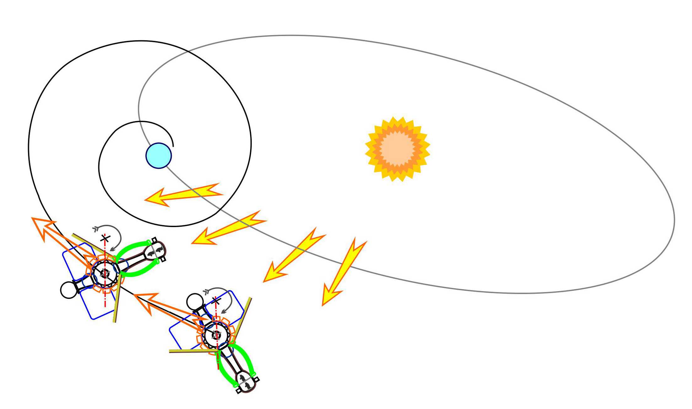
Presumably, such station will be able to carry out of independent output from its elliptical orbit to geostationary, go out from geostationary into the Lagrange point L1 and then to carry out a flight to Mars or carry out few subsequent "gravity turn" for executing the "gravity cannon" for carrying out route to a few points in during of feasible time of living of the station in autonomous mode.